

10G fgOTN Analyser
key word:
Category:
Products
Transmission Test
describe
10G fgOTN Analyser
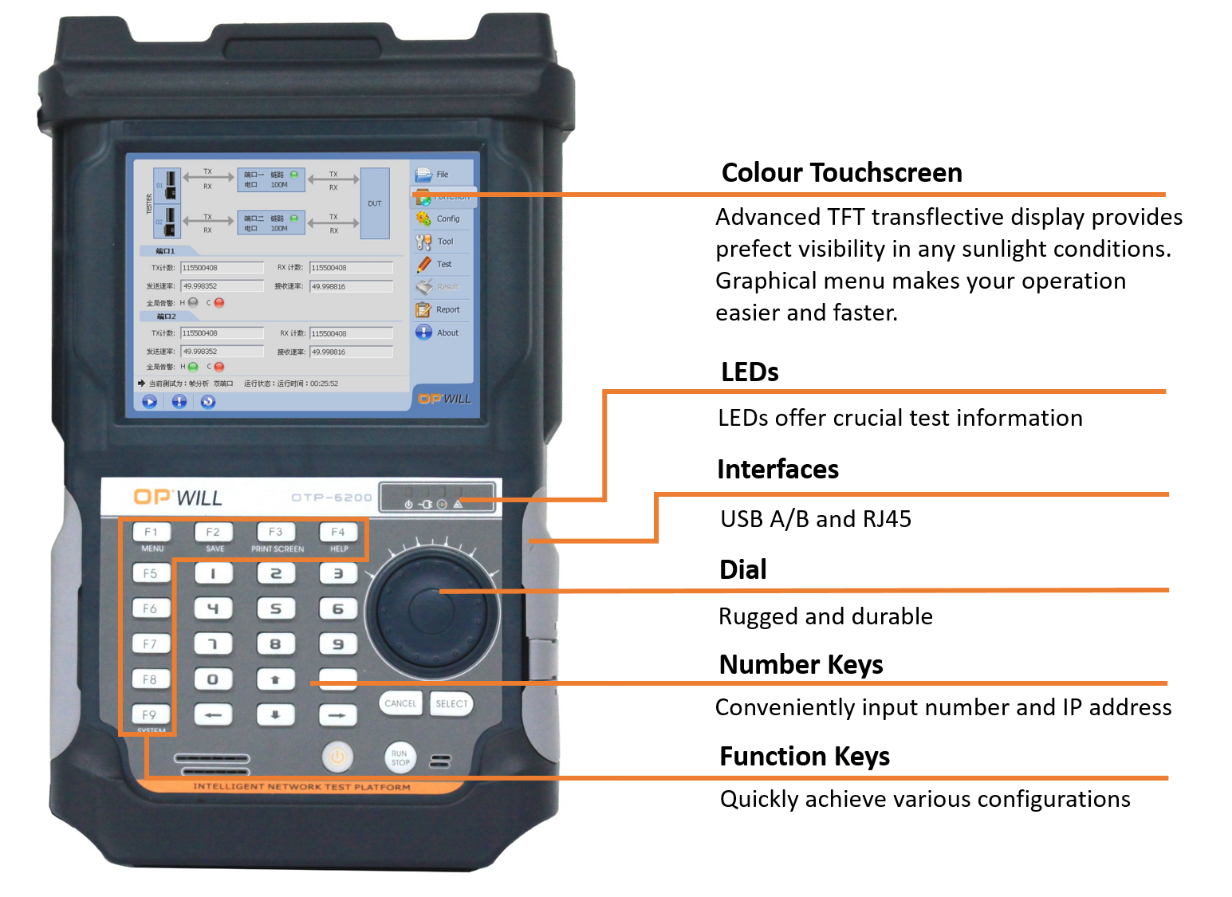
OPfg-01 10G fgOTN is a multi service comprehensive testing instrument created by OPWILL, which integrates testing solutions for OTN, SDH, SONET, PTN, Ethernet and other transmission and data. Equipped with the latest standards and testing methods of fg-OTN and OTU0, we provide testing tools for mobile operators, equipment suppliers, and communication engineering construction units to develop, construct, open, accept network testing, maintain and troubleshoot transmission networks, data networks, and synchronous networks. Provide users with a cost-effective, high-performance, and high-precision integrated testing instrument for 5G/6G network activation
The intelligent network testing platform provides flexible scalability and supports OTN by selecting different testing modules, SDH/SONET, MSTP, PDH/DSn, PTN/IP RAN, SyncE, IEEE1588v2 PTP, OTDR, Ethernet, fiber optic cable survey instrument, 100G and other testing functions.
- Design a robust, compact, portable, and powerful modular intelligent network testing platform;
- Rich button design, supporting numeric and function keys, convenient and flexible input and selection;
- Remote access and control based on Ethernet;
- Dual port or four port OTN, SDH, SONET, PTN, IP RAN, and Ethernet testing functions integrated.
Platform Briefs:
|
|
|
|
|
|
|
|
|
Key Feature:
OTN:
|
|
|
|
|
|
|
|
Ethernet:
|
|
|
|
|
|
|
|
|
|
|
|
SDH/SONET:
|
|
|
|
|
|
Test Application:
- fgOTN equipment research and development, production testing;
- fgOTN equipment networking and debugging, installation and testing;
- OTN/SDH/SONET on-site installation, debugging, and service activation;
- DSn/PDH to SONET/SDH testing, up to OC-192/STM-64;
- Online testing, offline testing, loop back delay testing, protection switching testing
- 10/100/100MBase-T, 100/1000MBase-X, and 10GE (LAN/WAN) BERT, RFC2544, Y.1564, and RFC6349 testing.
- Grouping network performance testing, network design testing.
General Specifications: OPfg-01
|
GENERAL SPECIFICATIONS |
|
|
User Interface |
|
|
Screen |
6.5 Inch TFT Touch Screen (640 x 480); |
|
Other Interface |
|
|
USB |
|
|
Ethernet |
Ethernet 10/100M, RJ45; |
|
Audio |
3.5mm Audio Interface; |
|
Storage |
16G; |
|
Physical Specifications |
|
|
Temperature |
|
|
Relative Humidity |
0% to 95%(non-condensing); |
|
Size(H×W×D) |
|
|
Weight |
|
|
Vibrancy |
10Hz to 500Hz < 1.5g (on 3 main axes); |
|
Mechanical Shock |
6 sides, 8 edges < 760cm, according to GR-196-CORE; |
|
EMC |
|
|
Battery and Power Supply |
|
|
Battery |
|
|
Power Source |
|
Technical Specifications: OPfg-01
|
OTN Test |
|||||||||
|
Port |
User selectable optical module: 1310nm, 1550nm. |
||||||||
|
Measurement |
|
|
|||||||
|
Operation |
|
|
|
||||||
|
The OTU, ODU and OPU overhead can be changed; and the FEC encoder and decoder can be set ON/OFF in any mode. |
|||||||||
|
Frame and Scramble |
Compliant with ITU-T G.709 and ITU-T G.709.20 standards FEC: Compliant with G.709, RS (255239) standard, can control on/off |
||||||||
|
Transmitter Clock |
|
|
|||||||
|
Received signal frequency |
|
||||||||
|
Scrambling |
|
||||||||
|
OTN alarm |
Detectable alarms: |
||||||||
|
|||||||||
|
|||||||||
|
|||||||||
|
|||||||||
|
|||||||||
|
|||||||||
|
Possible alarms that can be generated: |
|||||||||
|
|||||||||
|
|||||||||
|
|||||||||
|
|||||||||
|
|||||||||
|
|||||||||
|
Alarm generation method: |
|||||||||
|
|
|
|||||||
|
OTN Error |
Detectable errors: |
||||||||
|
|||||||||
|
|||||||||
|
|||||||||
|
|||||||||
|
|||||||||
|
Possible errors: |
|||||||||
|
|||||||||
|
|||||||||
|
|||||||||
|
|||||||||
|
|||||||||
|
Incorrect insertion method: |
|||||||||
|
|
|
|
|
|||||
|
Mapping adjustment |
Mapping adjustment (for each AMP) |
||||||||
|
|||||||||
|
|||||||||
|
|||||||||
|
Cm (t) (per GMP) |
|||||||||
|
|||||||||
|
Bit Error Test Pattern |
Support the generation and detection of the following patterns: |
||||||||
|
|||||||||
|
Support reverse PRBS pattern |
|||||||||
|
|||||||||
|
FEC Test |
|
||||||||
|
Overhead |
Users can edit the following frame header bytes: |
||||||||
|
|||||||||
|
|||||||||
|
|||||||||
|
|||||||||
|
Support capturing and displaying current overhead byte information: |
|||||||||
|
|||||||||
|
Support capturing consecutive 256 frames of overhead bytes |
|||||||||
|
OTU0 |
Support OTU0 standard testing and adding business parameters such as net load GFP-F; |
||||||||
|
Main path mapping structure: |
|||||||||
|
|||||||||
|
|||||||||
|
|||||||||
|
|||||||||
|
|||||||||
|
Through Mode |
|
||||||||
|
|||||||||
|
The overhead of OUT, ODU, and OPU can be changed |
|||||||||
|
FEC encoding and decoding can be set to on/off |
|||||||||
|
fgOTN Test |
|||||||||
|
Mapping Path |
PRBS、ETH、CBR、VCN->fgODUflex->ODU2->OTU2 PRBS、ETH、CBR、VCN->fgODUflex->ODU1->ODU2->OTU2 PRBS、ETH、CBR、VCN->fgODUflex->ODU0->ODU1->ODU2->OTU2 PRBS、ETH、CBR、VCN->fgODUflex->ODU0->ODU2->OTU2 PRBS、ETH、CBR、VCN->fgODUflex->ODUFlex(3,4,5,6,7)->ODU2->OTU2 PRBS、ETH、CBR、VCN->fgODUflex->ODU1->OTU1 PRBS、ETH、CBR、VCN->fgODUflex->ODU0->ODU1->OTU1 PRBS、ETH、CBR、VCN->fgODUflex->ODU2->OTU2 |
||||||||
|
Overhead editing and monitoring |
Cost sequence setting/reading |
fgODUflex |
PM-TTI、TCMi-TTI |
||||||
|
fgOPUflex |
PT、CSF |
||||||||
|
OPUk(fgTS) |
fgTSMxOH |
||||||||
|
Cost setting/display |
fgODUflex |
FAS0~FAS7,STAT(row1~4)、PM&TCM、 TCMi-APS、PM-APS、DAi, RES |
|||||||
|
fgOPUflex |
RES |
||||||||
|
1. PM-TTI and TCMi TTI can set the cost sequence according to the protocol and display ASCII characters 2. All frames can be set to have the same overhead |
|||||||||
|
Overhead capture/display |
Content |
Can capture the overhead sequence of fgODUflex frames at any specified coordinate, Coordinate range: ROW=1~4,COL=1~16,1905~1920 |
|||||||
|
Mode |
Continuous capture (manual trigger mode, change trigger mode), change capture |
||||||||
|
Capacity |
256 Bytes |
||||||||
|
Display |
Raw data (hexadecimal), ASCII characters |
||||||||
|
Error code alarm insertion and monitoring |
1. Alarm and error codes that can be unplugged in the fgODUflex layer PM: Error code: PM_BIP8, PM_BEI, FAS,MFAS give an alarm: PM_BDI, PM_LCK, PM_OCI, PM_AIS, Alarm and error codes available for monitoring: Error code: PM_BIP8, PM_BEI, FAS_BIT, MFAS_BIT, DM_CRC12 give an alarm: LOF, LOM, OOF, OOM, PM_OCI, PM_BDI, PM_LCK, PM_SAPI_TIM, PM_DAPI_TIM Support rewriting and monitoring of PM TTI TCM insertable alarms and errors: Error code: TCM_BIP8, TCM_BEI give an alarm: TCM_SAPI, TCM_DAPI_TIM, TCM_BIAE, TCM_BDI, TCM_AIS, TCM_LTC, TCM_OCI, TCM_LCK, TCM_IAE Alarm and error codes available for monitoring: Error code: TCM_BIP8, TCM_BEI, TCM_DM_CRC12 give an alarm: TCM_SAPI, TCM_DAPI_TIM, TCM_BIAE, TCM_BDI, TCM_AIS, TCM_LTC, TCM_OCI, TCM_LCK, TCM_IAE, TCM_SAPI_TIM, TCM_DAPI_TIM Support rewriting and monitoring of TCM TTI 2. Alarm and error codes that can be unplugged in the fgOPUflex layer: Error code: CMT_CRC8, CND_CRC5, RCOH_CRC3 give an alarm: CSF, PLM, CM0 Alarm and error codes available for monitoring: Error code: PRBS_BIT,CM_CRC8, CN_CRC5, RCOH_CRC3, OFCS, OMFI give an alarm: OPU_PLM, OPU_CFS, LSS, OOMFI, LOOMFI, CM_LOS, CM |
||||||||
|
Non destructive adjustment testing |
Non destructive adjustment test values can be edited and displayed through schematic diagrams |
||||||||
|
Bidirectional latency test |
Content |
Total number of measurements, number of successful measurements, number of failed measurements, minimum value Maximum value, average value, current value |
|||||||
|
Test selection |
PM、TCM1、TCM2 |
||||||||
|
Range |
0s ~ 60s |
||||||||
|
Accuracy |
1us |
||||||||
|
Testing mode |
two-way |
||||||||
|
Service Interruption Test |
Monitoring trigger conditions |
||||||||
|
Alarm |
fgODUflex |
LOFLOM、LOFOOM、PM-BDI、PM-AIS、PM-OCI、PM-LCK、PM-SAPI-TIM、PM-DAPI-TIM |
|||||||
|
fgODUflex-TCM |
TCMi-BDI、TCMi-AIS、TCMi-OCI、TCMi-LCK、 TCMi-BIAE、TCMi-SAPI-TIM、TCMi-SAPI-TIM |
||||||||
|
fgOPUflex、OPUk(fgTS) |
OOMFI、LOOMFI、PLM、CSF |
||||||||
|
fgOPUflex-GMP、 |
Loss of Synchronization Cm=0 |
||||||||
|
Bit Error |
fgODUflex |
PM-BIP8、PM-BEI |
|||||||
|
fgODUflex-TCM |
TCMi-BIP8、TCMi-BEI |
||||||||
|
fgOPUflex、 |
OMFI |
||||||||
|
fgOPUflex-GMP |
CRC-5、CRC-8 |
||||||||
|
OPUk(fgTS)-fgGMP |
CRC-4 |
||||||||
|
fgTSMxOH |
CRC-6 |
||||||||
|
fgBWR RCOH |
CRC-3 |
||||||||
|
DM |
CRC-12 |
||||||||
|
Packet client |
fgOFFCS |
||||||||
|
Payload |
CLIENT-Error |
||||||||
|
Test Result |
|||||||||
|
statistics |
content |
Number of interruptions, maximum, minimum, average, total |
|||||||
|
|
List the time and length of each interruption, which can be recorded 50 times |
||||||||
|
Range |
0~10s |
||||||||
|
precision |
0.01ms |
||||||||
|
Unit |
ms, s, min |
||||||||
|
GMP mapping mode |
fgOPUflex-GMP/OPUk(fgTS)-fgGMP mapping method |
||||||||
|
Cmt |
method |
Reference value, actual maximum value, minimum value, average value, current value |
|||||||
|
Separate statistics for the transmit and receive sides |
|||||||||
|
TCM testing |
Transmit Side |
2-level TCM Independent Enable |
|||||||
|
SAPI、DAPI |
|||||||||
|
Receive Side |
2-level TCM Independent Enable |
||||||||
|
Display Received and Set Expected: SAPI, DAPI |
|||||||||
|
OTN test results |
|||||||||
|
Status |
Current Information
|
||||||||
|
Statistics |
Log Information: Alarms (in seconds), Errors (number or number and ratio) |
||||||||
|
Histogram |
All errors and alarms are displayed graphically, allowing users to view all issues at a glance. |
||||||||
|
APS |
APS (Automatic Protection Switching) testing and analysis:
APS switching time measurement resolution: 0.01ms |
||||||||
|
Loopback Delay Measurement |
Resolution: 1us Maximum test time: 60.0s |
||||||||
|
TECHNICAL SPECIFICATIONS |
|
|
Ethernet |
|
|
Port |
User selectable optical module: 850nm, 1310nm, 1550nm. |
|
Ethernet Feature |
Auto negotiation, flow control; |
|
Configuration |
Monitor/Generate, pass-through; |
|
Encapsulation |
Ethernet type II, IEEE802.3 with 802.2, IEEE802.3 with SNAP; |
|
Configuration, Monitoring, and Generation |
|
|
Traffic Generation |
|
|
Stacked VLAN |
|
|
Multi stream |
Number of streams: up to 512streams per port can be activated; |
|
Error Injection |
FCS, IP check sum error, UDP/TCP check sum Error, bit error, BER test sequence error; |
|
Alarm generation |
No link; |
|
Result, Monitoring and Generation |
|
|
Status |
|
|
Performance Statistics |
Utilisation, throughput,frame rate; |
|
Frame Statistics |
|
|
Result, Monitoring and Generation |
|
|
Frame Distribution Statistics |
|
|
Multi stream |
Display information per steam:
|
|
Transmit Statistics |
Total frames, unicast/multicast/broadcast; |
|
Filter |
Filter condition support:
|
|
BER Test and Service Disruption Test |
|
|
BER Test |
|
|
Error Injection |
FCS, IP check sum error, UDP/TCP check sumerror, BIT error, BER test sequence error; |
|
Service Disruption Test |
Service disruption test activated as part of BER test:
|
|
Loopback |
|
|
Loopback Test |
|
|
RFC2544 |
|
|
RFC2544 Test |
|
|
Service Activation Test (Y.1564) |
|
|
Service Activation Test |
ITU-T Y.1564 service activation test:
|
|
Service Configuration Test |
|
|
Service Performance Test |
|
|
Remote Smart Loopback Test |
|||||
|
Remote Smart Loopback |
|
||||
|
Advanced IP Tools |
|||||
|
PING |
For connectivity and configuration check: |
||||
|
|
||||
|
Trace Route |
Trace IP route over IP network:
|
||||
|
VCT Cable Test |
Use for CAT5 cable connectivity check: |
||||
|
|
|
|||
|
Flow Control |
Flow control time, us: |
||||
|
|
||||
|
FTP Upload/ Download |
Use for FTP server and client emulation: |
||||
|
|
||||
|
HTTP |
WEB access: |
||||
|
|
||||
|
Advanced PING (Topology) |
Advance/fast PING, PING segments of the IP one by one in one time: |
||||
|
|
||||
| MPLS | |||||
|
Number of MPLS Header |
Up to 3 MPLS header set by user; |
||||
|
Parameter per MPLS Header |
User defined label, exp and TLL fields in each MPLS header:
|
||||
|
Statistics |
MPLS frame count; |
||||
| Ethernet Frame Capture | |||||
|
Capture Buffer Size |
|
||||
|
Capture Frame Slicing |
Can capture frame length by user defined; |
||||
|
Capture Data |
CAP format for display in Wireshark. |
||||
|
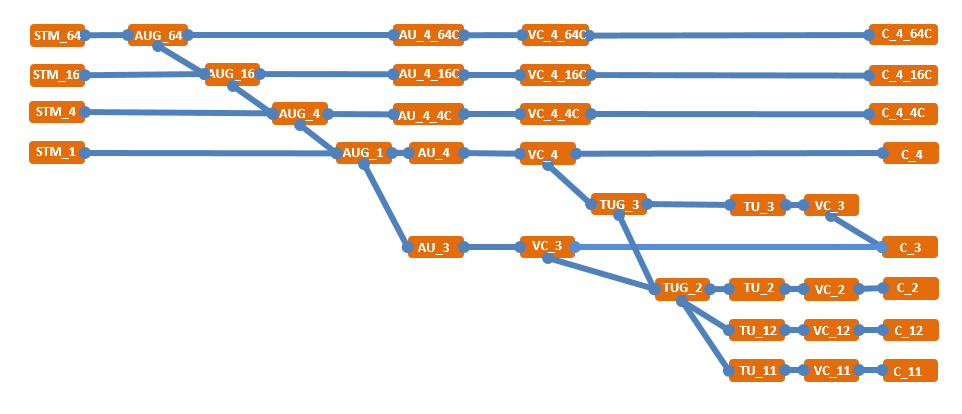
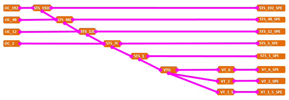
SDH and SONET Test |
||||||||
|
Port |
User selectable optical module:850nm/1310nm, 1550nm |
|||||||
|
Measurement |
|
|
||||||
|
Operation |
|
|
|
|||||
|
Can be changed SOH/TOH, can injection alarms and errors under Enhance Through Mode. |
||||||||
|
Frame and Scramble |
|
|||||||
|
Line Code |
NRZ |
|||||||
|
Transmitter Clock |
|
|
||||||
|
Receive Single Rate |
|
|||||||
|
TCM Frame Format |
|
|||||||
|
|
|
|
|
||||
|
||||||||
|
SDH Mapping |
||||||||
|
|
||||||||
|
SONET Mapping |
||||||||
|
|
||||||||
|
Alarm |
Alarm can to be detected and generated:
|
|||||||
|
||||||||
OPfg-01 Ordering Information
|
SDH and SONET Test |
||||||||
|
Alarm |
|
|||||||
|
Alarm generation mode: |
||||||||
|
|
|
||||||
|
Error |
Error can be detected and generated:
|
|||||||
|
Error generation mode: |
||||||||
|
|
|
|
|
|
|||
|
BERT Pattern |
Support to generate and detect:
Support reversed PRBS pattern:
|
|||||||
|
Pointer |
|
|||||||
|
Overhead |
|
|||||||
|
SDH Tributary Scan |
|
|
||||||
|
SONET Tributary Scan |
|
|
||||||
|
Smart Scan |
Remote single auto detects and auto setup for SDH/SONET analyser; |
|||||||
|
SDH and SONET Result |
||||||||
|
Status |
Display information of current status: |
|||||||
|
|
|
||||||
|
Statistics |
Event log display: |
|||||||
|
|
|
||||||
|
Histogram |
All alarms and errors detected can be display in histogram; |
|||||||
|
Error Performance |
G.821/G.826/G.828/G.829/M.2100/M.2110 analysis of received signals based on detected errors and alarms: ES, SES, BBE, AS, UAS, and so on; |
|||||||
|
APS |
APS (Automatic protection switching):
APS time resolution: 1us; |
|||||||
|
Propagation Delay Measurement |
|
|||||||
|
OPfg-01 STANDARD CONFIGURAIOTN |
|
|
Module |
Description |
|
Platform |
OPfg-01 10G fgOTN Analyser |
|
Accessories Code |
Accessories Description |
|
16080010 |
LC/PC to LC/PC full-duplex single-mode fibre, 3 meters, one; |
|
16060040 |
CAT5 cable, 3 meters, one; |
|
14020180 |
10G 1310nm 10Km LC SFP+ optical modules, two; |
|
05020050 |
SFP/SFP+ optical port dust proof cap - black - rubber, two; |
|
05020060 |
RJ45 electrical port dust proof cap - black - rubber, two; |
|
16060010 |
3 pins adapter cable, one; |
|
43170020 |
100-240V input and 19V output AC/DC power adapter, one; |
|
18080010 |
Disc include user manual and OPWILL remote control software, one; |
|
19070010 |
Instrument package, one; |
|
18010010 |
Factory test report, one; |
|
18010020 |
Calibration certificate, one; |
|
18040011 |
One year warranty service. |
|
10G fgOTN OPTIONAL CONFIGURATION |
|
|
Optional Software (ETH) |
|
|
OPAP-Y1564TGeEth |
Y.1564 standard service configuration and performance test for SLA QoS with CIR/EIR/Traffic Dropped up to 10GE; |
|
OPAP-DPY1564TGeEth (Need to order OPAP-Y1564TGeEth first) |
Bi-directional Y.1564 test; |
|
OPAP-RFC6349TGeEth |
RFC6349 TCP throughput test features; |
|
OPAP-IPv6TGeEth |
IPv6 feature, the test interface can set IPv6 address and can generate stream with IPv6; |
|
OPAP-ScanTGeEth |
Traffic scan according with destination MAC/IP, source MAC/IP, 3 Layer VLAN, 3 Layer MPLS in-service test; |
|
OAPA-EPINGTGeEth |
Advance/Fast PING, PING segments of the IP one by one in one time; |
|
OPAP-3MPLSTGeEth |
Up to 10G rates generation with 3 Layer MPLS label; |
|
OPAP-128StreamsTGeEth |
Up to 128 streams generation and analysis with MAC/VLAN/IP/TCP/UDP for 10G port; |
|
OPAP-512StreamsTGeEth |
Up to 512 streams generation and analysis with MAC/VLAN/IP/TCP/UDP for 10G port; |
|
OPAP-EautoAGeEth |
Advance auto-negotiation, can set the remote equipment auto-negotiation the speed and duplex as you want; |
|
OPAP-DPRFC2544AGeEth |
Enhancement RFC2544 test, support different upstream and downstream rates setup for Throughput, Frame Loss and Back-to- Back test; |
|
OPAP-FXAGeEth |
Dual 100M Base-X optical ports; |
|
OPAP-10GWANATGeEth |
10GE WAN Test Function; |
|
Optional Software (SDH and SONET) |
|
|
OPAP-ThroughTGeSDH |
SDH/OTN Enhanced Through Function; |
|
OPAP-TCMTGeSDH |
TCM Test; |
|
Optional Software (OTN) |
|
|
OPAP-OHSeqCapture |
256 frames OTN overhead capture and decode capability |
|
OPAP-ODU0Mapping |
ODU0 mapping capability test |
|
OPAP-ODUflexMapping |
ODU flex mapping capability test |
|
OPAP-TCM |
TCM Test |
|
OPAP-RFC2544 |
RFC2544 (when the payload is ETH, can be used) |
|
Optional Hardware |
|
|
43160031 |
OTP6200 lithium polymer rechargeable battery; |
|
OPAP-Onewarranty |
One year extended warranty service; |
|
OPAP-Twowarranty |
Two years extended warranty service; |
Notes: Product ordering information may update along with the product upgrade, please refer to the final version provided by our sales.
Related products

FTS510 -- Series Handheld OTDR Tester
Get product quotes for free
Contact us
Address: RoomA-1445, Level 6, No.28 Shangdi Information Road, Haidian District, Beijing, PRC.
Postal code: 100085
Tel:+86 10 82771386/2866/3382
Fax:+86 10 82771782
400 hotline: 400 630 3382
Website: www.opwill.com
OPWILL not only serves major domestic operators, equipment manufacturers, private network users and communication service contractors, but also sells to more than 30 countries and regions in the world.
© 2024 OPWILL Technology (Beijing) Co., Ltd